Unlike Intel x86, which is the prevailing computer architecture that is CISC (Complex Instruction Set Computer) based, ARM is RISC (Reduced Instruction Set Computer), meaning that most instructions are made from just a smaller set of instructions, allowing them to execute quickly and consistently.
It is often used from hardware that require low power, such as Raspberry Pis, to high performance, like the M-series chips from Apple and the Steam Deck.
It is also a lot more simple to learn.
Instruction Modes
ARM processors can operate in one of two instruction modes: ARM mode and Thumb mode.
In ARM mode, the processor executes full 32-bit instructions. This mode offers the full instruction set and is generally used when performance is a priority.
On the other hand, Thumb mode uses 16-bit compressed instructions. While these are less flexible, they take up less space in memory, which can be a big advantage in embedded or memory-constrained environments.
Data Types
ARM supports working with data of different sizes, and each size has specific load instructions. The data widths are:
- A double-word, which is 64 bits.
- A word, which is 32 bits.
- A half-word, which is 16 bits.
- A byte, which is 8 bits.
They can also be signed or unsigned.
To load these values from memory, ARM uses different instructions that are tailored to the data type, indicated by the suffix of the opcode.
ldr    // Loads a 32-bit word
ldrh   // Loads a 16-bit half-word
ldrsh  // Loads a signed 16-bit half-word
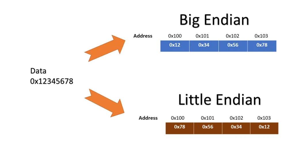
Endianness
ARM supports both little-endian and big-endian formats for reading bytes.
In little-endian mode, the least significant byte is stored first, which is the standard on most ARM systems.
Big-endian mode, on the other hand, stores the most significant byte first.
Registers
General Purpose Registers
ARM includes 30 general-purpose registers, but in most user-level programming, you’ll interact with only the first 16. These are labeled from r0 to r15, each serving a specific or general role.
-
r0tor12are used for general data storage and computation. You can think of them as scratchpads during your program’s execution. -
r13, more commonly referred to as the Stack Pointer (sp), points to the top of the call stack. This is where local variables and function return addresses live during program execution. -
r14, known as the Link Register (lr), holds the return address when a function call is made. When you call a function, ARM saves the current execution point in lr, so it knows where to come back after the function finishes. -
r15, or the Program Counter (pc), always points to the address of the instruction currently being executed. It automatically increments as the program runs—by 8 bytes in ARM mode and 4 bytes in Thumb mode.
CPSR
The Current Program Status Register (CPSR) tracks the state of the processor, through a series of flags, which are useful for writing conditional logic in assembly. Flags include:
-
N(Negative): Set if the result of an operation is negative. -
Z(Zero): Set if the result is zero. -
C(Carry): Indicates a carry out from arithmetic operations. -
V(Overflow): Indicates signed overflow occurred. -
E(Endianness): Shows whether the system is using little or big endian. -
T(Thumb): Indicates if the processor is in Thumb mode. -
M(Mode bits): Define the current privilege level or operational mode. -
J(Jazelle): Some ARM cores have a special execution state that allows the CPU to run Java Bytecode natively.